
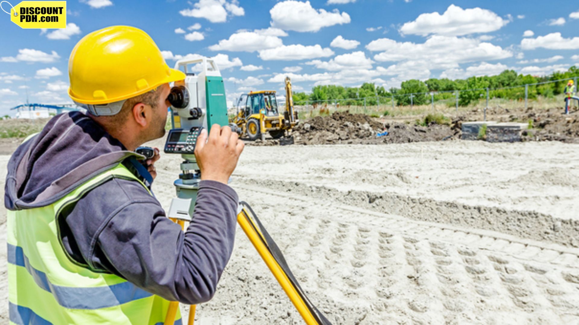
Digital terrain models help surveyors estimate cut-and-fill volumes, but small data or surface errors can create costly quantity differences. Incorrect ground classification, sparse survey points, missing breaklines, and mismatched coordinate systems can distort results. This blog post explains how to inspect terrain data, verify earthwork calculations, compare surfaces, and document findings before quantity estimates are used for bids or construction decisions.
Why a Digital Terrain Model Can Mislead
A digital terrain model (DTM) can look smooth on screen while producing earthwork quantities that fail to represent actual site conditions. Small errors in surveyed elevations, ground classification, or surface geometry can affect excavation and fill estimates across a large construction site.
Professionals exploring land surveying PDH courses can strengthen their understanding of topographic data, construction measurements, and surface modeling through relevant technical training. Knowing how to check a model before accepting its volume report helps surveyors provide more dependable information to contractors, engineers, and project owners.
Start With the Original Survey Data
A surface model cannot correct bad measurements automatically. Before examining the calculated volumes, review the source data collected through total stations, GNSS receivers, drone photogrammetry, or LiDAR.
Check for unexplained elevation spikes, duplicate observations, gaps in point coverage, and measurements that disagree with nearby terrain. Pay particular attention to steep slopes, narrow drainage channels, and areas beneath heavy vegetation, where collecting reliable ground elevations can be difficult.
Ground classification also matters. If vegetation or other objects are incorrectly classified as bare earth, the model may represent the tops of plants rather than the ground beneath them. The resulting elevation difference can distort the amount of material estimated for excavation or embankment.
The US Geological Survey explains relevant data-quality considerations in its LiDAR Base Specification, including ground-point classification, reference systems, and independent accuracy checks.
Inspect Breaklines and Surface Geometry
Survey software commonly creates a triangulated irregular network (TIN) by connecting measured points into triangular facets. Raster elevation models represent the terrain differently, using cells arranged in a grid. Either method can produce a misleading surface when important ground features are missing.
Breaklines help preserve features that define changes in terrain, such as ditch bottoms, road crowns, curb edges, and the tops or toes of embankments. Without suitable breaklines, a TIN may connect points across a ditch instead of following its actual shape.
Imagine a site where a drainage channel runs between two gently sloping areas. If the model bridges the channel, it may show a higher ground surface than exists on site. Comparing that surface against a proposed grade can then understate the excavation required.
Review the model in plan view and in cross-sections. Look for artificial ridges, unexpected depressions, flat surfaces across sloping ground, and triangles that cut across physical features. These checks can reveal defects that a shaded three-dimensional view might hide.
Confirm Coordinate Systems and Elevation References
Two surfaces may each appear reasonable but still fail to align because they use different coordinate systems, vertical datums, or units.
Check the horizontal reference system, vertical datum, elevation units, and any transformations applied during processing. The existing-ground model and the proposed design surface must use compatible references before their elevation differences can produce meaningful volume calculations.
For example, combining a survey measured in meters with a design expressed in feet without proper conversion creates a serious mismatch. A vertical reference error can also shift an entire surface, causing the software to report excessive excavation or fill across much of the site.
Compare known control points and verified elevations with the model. If the discrepancies follow a consistent pattern, investigate the reference system before editing individual measurements. The National Geodetic Survey’s guidance on vertical datums provides useful background on elevation references used in surveying.
Compare Existing Ground With the Proposed Surface
Earthwork calculations generally compare the existing terrain with the proposed design elevations. The difference between these surfaces identifies areas where material must be removed and locations requiring fill.
Review the cut and fill distribution rather than relying only on the final totals. A large excavation pocket in an otherwise level area may signal an incorrect elevation, a surface artifact, or a design feature that deserves closer inspection.
Consider a simplified example. An average vertical discrepancy of 0.10 foot across 100,000 square feet represents approximately 370 cubic yards of volume difference. Actual terrain varies, so this calculation illustrates the potential impact of a uniform elevation error rather than predicting the quantity for a real site.
The same surface checks matter when finished grades connect to landscape areas. Incorrect elevations can affect drainage paths, planting areas, and the movement of excess irrigation water. For related hydraulic considerations, see Landscape Irrigation Design: Pressure, Flow, and Distribution Efficiency, which connects landscape water distribution with basic irrigation hydraulics.
Audit the Volume Calculation Settings
Even a sound surface can produce misleading quantities when the calculation boundaries or project assumptions are wrong.
Before approving a report, review these items:
- Project limits: Confirm that the calculation includes the intended work area and excludes unrelated ground.
- Cross-section spacing: Check that sections capture important terrain changes when using the average end-area method.
- Cut-and-fill quantities: Verify that excavation and embankment figures are reported separately and that the software uses the intended reference surfaces.
- Topsoil and material adjustments: Confirm how stripping, shrinkage, swell, and compaction are handled in the quantity estimate.
The Federal Highway Administration’s Earthwork Design guidance describes the average end-area method, which calculates volume from adjacent cross-sectional areas and the distance between them. Digital surface-to-surface methods use a different calculation approach, so the chosen method should match the project requirements.
One important distinction is the difference between geometric volume and the amount of material transported or placed. Soil can expand after excavation and contract during compaction. These changes influence hauling and fill planning, but they are separate from errors in the terrain model itself.
Validate Results With Independent Checks
A software report is not independent proof that a DTM represents the actual ground. Surveyors should test the model against reliable observations that were not used to build the surface.
Select checkpoints across representative site conditions, including relatively flat ground, slopes, and areas where the terrain changes sharply. Compare the observed elevations with corresponding model elevations, then assess the differences against the project’s accuracy requirements.
If the checks reveal unacceptable discrepancies, investigate their pattern and source before recalculating earthwork quantities. Additional field observations, corrected point classifications, or revised breaklines may be necessary.
Keep the original data, revised surfaces, calculation settings, and verification results. A clear record allows another professional to understand how the estimate was prepared and why changes were made.
Strengthen Surveying Practice Through DiscountPDH
Reliable earthwork estimates depend on sound field measurements, suitable surface models, and careful quantity checks. DiscountPDH offers Construction Surveying – Earthwork, an online course listed for 2 Professional Development Hours (PDH). Its course material covers earthwork volume calculations, final grades, cut-and-fill balancing, and economical material hauling.
Surveyors can explore the full land surveying PDH course catalog for additional training in surveying fundamentals, topographic mapping, coordinate systems, and related technologies.
Professional responsibility matters alongside technical ability. Surveyors considering Land Surveyors Ethics courses can review DiscountPDH’s General Ethics and Standards for Professional Engineers and Land Surveyors, listed for 3 PDH hours. Accurate reporting, honest disclosure of limitations, and clear documentation support responsible professional decisions.
Confirm course acceptance with the relevant licensing board before relying on any course for renewal credit.
Make Survey Quantities Defensible
Earthwork estimates influence bids, construction planning, material movement, and payment decisions.
Checking the source measurements, model geometry, reference systems, and calculation settings gives surveyors a stronger basis for reporting quantities.
Answers to Common Questions About DTM Earthwork
Q1. What is the main purpose of a digital terrain model in earthwork?
A1. A DTM represents the ground surface and supports grading analysis, elevation comparisons, contour generation, and excavation or fill estimates.
Q2. How does a DTM differ from a digital surface model?
A2. A DTM generally represents bare-earth terrain, while a digital surface model may include features such as buildings and vegetation. Software terminology can vary, so confirm how each dataset was created.
Q3. Is a TIN always more accurate than a raster elevation model?
A3. No. Accuracy depends on source measurements, terrain complexity, resolution, processing, and the intended use. Neither format guarantees a reliable result on its own.
Q4. How should surveyors choose independent checkpoints?
A4. Choose reliable points that represent the site’s terrain and are independent of the observations used to create the model. Follow the project’s required accuracy standard and validation method.
Q5. Can drone surveys support earthwork quantity calculations?
A5. Yes, when collection conditions, ground control, processing, and accuracy checks are suitable for the project. Vegetation and inaccessible ground can limit the usefulness of drone-derived terrain data.
Q6. Why might two surveying software packages report different volumes?
A6. They may use different surface boundaries, triangulation settings, interpolation methods, grid sizes, or volume calculation procedures. Compare the settings before deciding that one result is incorrect.
Q7. Should topsoil stripping appear in an earthwork quantity report?
A7. It should be accounted for when required by the project’s scope and measurement rules. Report stripping separately when needed to distinguish it from bulk excavation and finished-grade quantities.
Q8. What should accompany a final earthwork quantity report?
A8. Include the source surfaces, reference systems, calculation limits, method used, relevant assumptions, and quality-control findings. These records make the results easier to review and reproduce.